BACKGROUND
Refrigerant leak sealants are quickly becoming popular tools to assist in extending the useful lives of refrigeration devices. They can slow or stop refrigerant leakage, allowing for the service lives of equipment to be improved, and for expensive service to be delayed or unnecessary. However, there has been highly reactive sealants marketed into the refrigeration and air conditioning industries which tend to form solids within the refrigeration circuit and result in equipment damage or failure.
Cool Seal is the refrigerant leak sealant marketed by Spectronics Corporation. It is specifically designed to collect around leak sites until the refrigerant flow is choked off or stopped entirely. It will not deposit within the interior of the refrigeration circuit, but only where the refrigerant is actively leaking into the exterior environment.
Other sealant products can form solids in the refrigerant lines which can severely affect the system’s operating performance or cause catastrophic system damage.
One of the most vulnerable parts of a refrigeration circuit which
depends on small clearances is the expansion device. This is used to allow for the phase change and cooling effect as a refrigerant passes from a liquid to vapor. Small changes to the internal shape and size of these parts will have a drastic effect on performance. One simple and effective expansion device, which is especially sensitive to blockages, is the capillary (cap) tube. These are simply small diameter tubes sized to restrict the refrigerant flow and allow for the pressure drop that is necessary for cooling. A sealant which will form solids and cause system damage will tend to collect in cap tubes and restrict refrigerant flow, or block it entirely. If cap tube flow rates can be monitored over time, there would be a good indication if something were happening within a refrigeration circuit that is producing solids and/or particulates.
The intent of this test is to demonstrate that Cool Seal will not form interior blockages within cap tubes, even if vastly overcharged into the equipment.
PROCEDURE
A test method was designed to allow for a small refrigeration circuit to be constructed using multiple sizes of cap tubes. See Figure 1. The flow through these cap tubes can be monitored over time, and the refrigerant and oil mixture flowing through them can be increasingly dosed with sealant. Any changes in a cap tube flow rate would be indicative of the formation of a blockage.
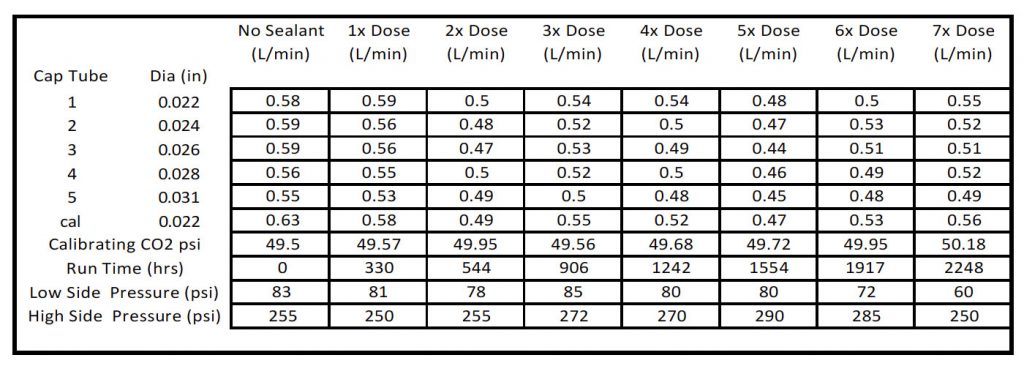
A small, self-contained air conditioning unit was opened and the refrigerant recovered. The system’s cap tube was removed, and the high-pressure liquid line was piped into a manifold which separated the flow into five separate cap tubes. The cap tubes used were ones commonly seen in the industry. The cap tube lengths were adjusted in order to maintain the proper system compression ratio and assure that the operating characteristics were as close as possible to those of the original design. These tubes allowed for parallel flow until they were routed into a second manifold where the refrigerant flow was then directed into the evaporator. The individual cap tubes were valved to allow for them to be isolated and then opened into the atmosphere, whereupon a measured stream of CO2 could be directed to flow through them. The flow rate of the CO2 was used as the metric to determine if any blockages were forming within the cap tubes. Once this flow rate was measured, the CO2 source was disconnected and the cap tubes were purged and brought back into the refrigerant stream. Flow data was taken through five differently sized cap tubes every two weeks.
The first readings were taken without any Cool Seal present, after which a full ½ ounce quantity of Cool Seal was added. As the test stand was constructed using a small window AC design, the ½ ounce of sealant represents a sealant overcharge. As the exact oil quantity in the test system was unknown, this dosage was used to represent a worst-case situation. Each subsequent flow data reading was followed by the addition of another ½ ounce of Cool Seal, until a total of seven doses (3.5 ounces) were added.
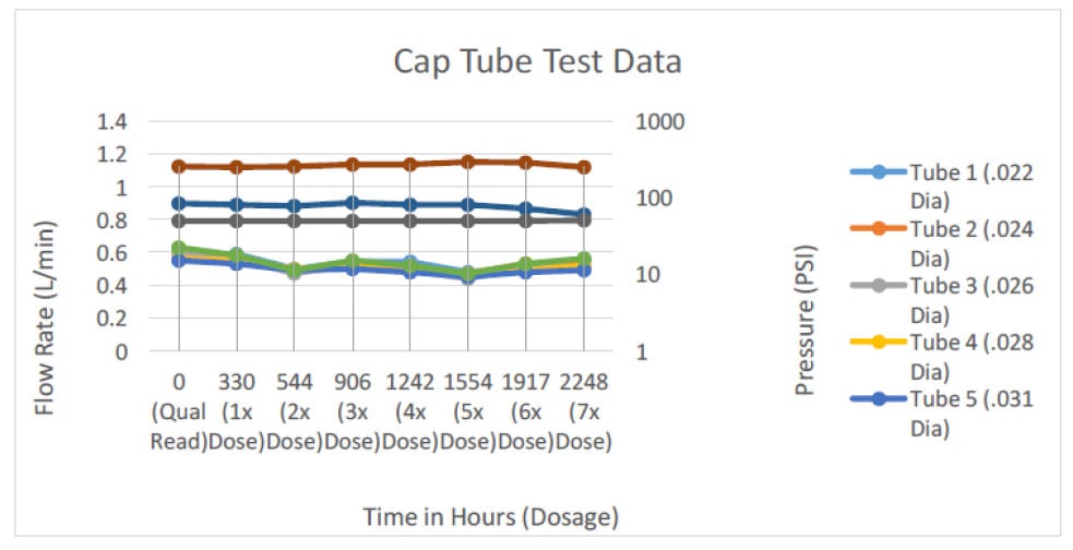
The system was also constructed with a separate calibration cap tube that was not exposed to any refrigerant flow. This allowed for the readings of the live cap tubes to be compared to that of the calibration cap tube, so that uncontrolled variables such as temperature, CO2 test pressure or humidity can be negated. If the readings derived from the calibration cap tube follow the same trends as those of the live cap tubes, the conclusion can be made that there were no blockages forming and any changes in flow rates observed were from uncontrolled external variables rather than internal system changes.
EQUIPMENT
Test Platform:
Frigidaire 5000BTU window unit AC. R-22 refrigerant.
Cap Tube sizes (From top of test stand down, inches diameter)
- 0.022
- 0.024
- 0.026
- 0.028
- 0.031
Calibration reference cap tube – 0.022 inched diameter (seen as vertical tube on left side of left manifold).
Calibration Equipment for test CO2 flow:
Fluke 700G07 pressure gauge
Gas Flow Equipment:
Brooks 2610A2A13SVVT variable area flow meter Dry CO2 regulated to 50 +/- 0.5psi
RESULTS


CONCLUSION
Cool Seal leak sealer will not form internal blockages even in scenarios in which it is used for extended periods and vastly overdosed above Spectronics’ recommended concentrations.
